Ta stran dokumentira dve ločeni validacijski zaporedji FFRS, prikazani v istem uradnem videoposnetku. 1. del je preizkus gašenja požara razreda A, pri katerem je FFRS pripravljeno testno kocko iz trdnega goriva pogasil s stalne varne razdalje 10 m v 4 minutah in 30 sekundah z enim vgrajenim rezervoarjem za vodo. 2. del je ločen 30-minutni preizkus toplotnega sevanja, pri katerem se je FFRS postopoma približeval viru sevalne toplote, medtem ko so termočleni merili temperature in se je ocenjevalo delovanje vodnega ščita. Rezultati obeh preizkusov so spodaj predstavljeni ločeno.
Oglejte si celoten dvodelni videoposnetek preizkusov FFRS
Videoposnetek združuje oba nadzorovana preizkusa v enem zaporedju, vendar ocenjujeta različne zmogljivosti. Prvi del prikazuje daljinsko gašenje požara razreda A. Drugi del ocenjuje toplotno izpostavljenost, izmerjeni temperaturni odziv in učinek vodnega ščita FFRS pri intenzivnem sevalnem segrevanju.
1. del – Preizkus gašenja požara razreda A
Prvi preizkus ocenjuje FFRS kot celovit daljinsko upravljan gasilski sistem proti pripravljenemu požaru razreda A s trdnim gorivom. Cilj ni bil zgolj prikaz pretoka vode, temveč izvedba celotnega operativnega zaporedja: ohranjanje določene varne razdalje, daljinsko usmerjanje vodnega monitorja, neprekinjen nanos vode in popolna pogasitev goreče testne kocke.
Požari razreda A vključujejo običajne trdne gorljive materiale, kot so les, papir, tekstil in podobna goriva. Ti materiali lahko po zmanjšanju vidnih plamenov še naprej tlijo, zato gašenje zahteva natančen nanos vode in nadaljnje hlajenje gorivne obremenitve.
Postavitev preizkusa in varna razdalja
FFRS je bil postavljen na stalno razdaljo 10 m od pripravljene testne kocke požara razreda A. Na tej razdalji je ostal skozi celoten postopek gašenja; stroj se ni postopoma približeval, da bi bilo gašenje lažje. Operater je platformo in vodni monitor upravljal na daljavo ter ostal ločen od neposrednega območja požara.
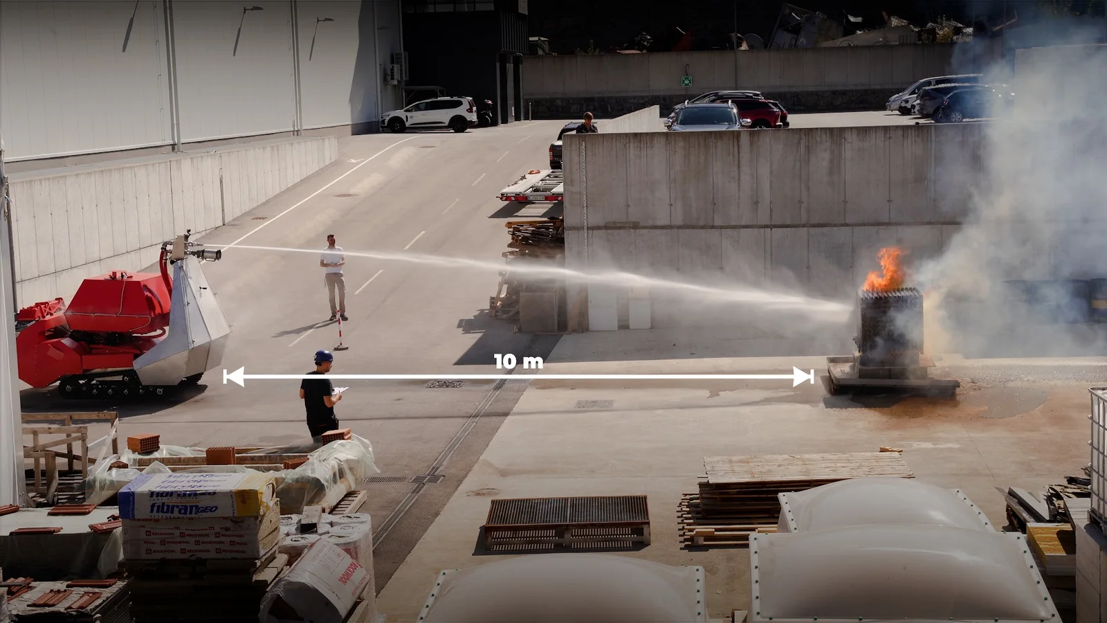
Potek gašenja
Z razdalje 10 m je operater daljinsko usmeril vgrajeni vodni monitor proti goreči gorivni obremenitvi. Nanos vode se je neprekinjeno prilagajal za gašenje vidnega plamena in hlajenje materiala, ko je bil požar postopoma obvladan. Stroj je skozi celotno zaporedje gašenja ostal na istem položaju.
Požar razreda A je bil v celoti pogašen po 4 minutah in 30 sekundah. FFRS je ta preizkus izvedel z enim vgrajenim rezervoarjem za vodo, brez potrebe po ponovnem polnjenju pred pogasitvijo.
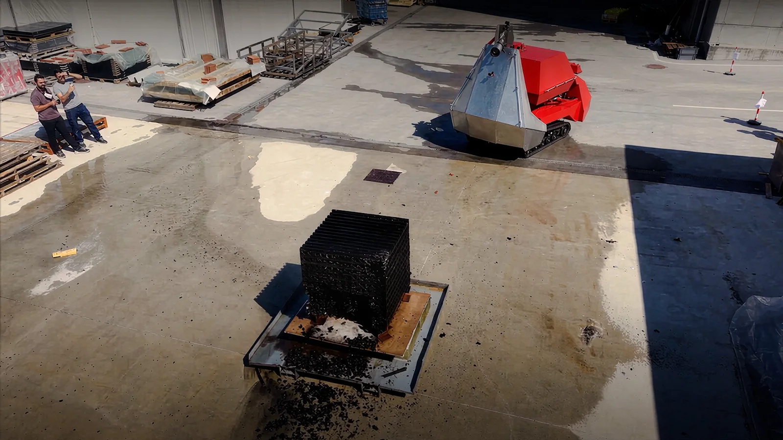
FFRS je pripravljen požar razreda A pogasil v 4 minutah in 30 sekundah s stalne varne razdalje 10 m z enim vgrajenim rezervoarjem za vodo. Ta rezultat velja posebej za nadzorovano testno konfiguracijo, prikazano v videoposnetku in fotografijah.
2. del – Preizkus toplotnega sevanja
Drugi del videoposnetka je ločen preizkus toplotnega sevanja. Zasnovan je bil za oceno obnašanja sistema FFRS pri naraščajoči izpostavljenosti sevalni toploti in za opazovanje učinka integriranega vodnega ščita na izmerjene površinske temperature. Ta notranji preizkus je ločen od zgornjega preizkusa gašenja požara razreda A; rezultat gašenja 4 minute in 30 sekund za ta del ne velja.
Za spremljanje temperature je ZAG na FFRS namestil termočlene v skladu z določenim načrtom merjenja s termočleni. Stroj je bil nato izpostavljen nadzorovanemu viru sevalne toplote in se je med preizkusom postopoma približeval. Temperature so bile spremljane na vsaki stopnji pred naslednjo spremembo razdalje.
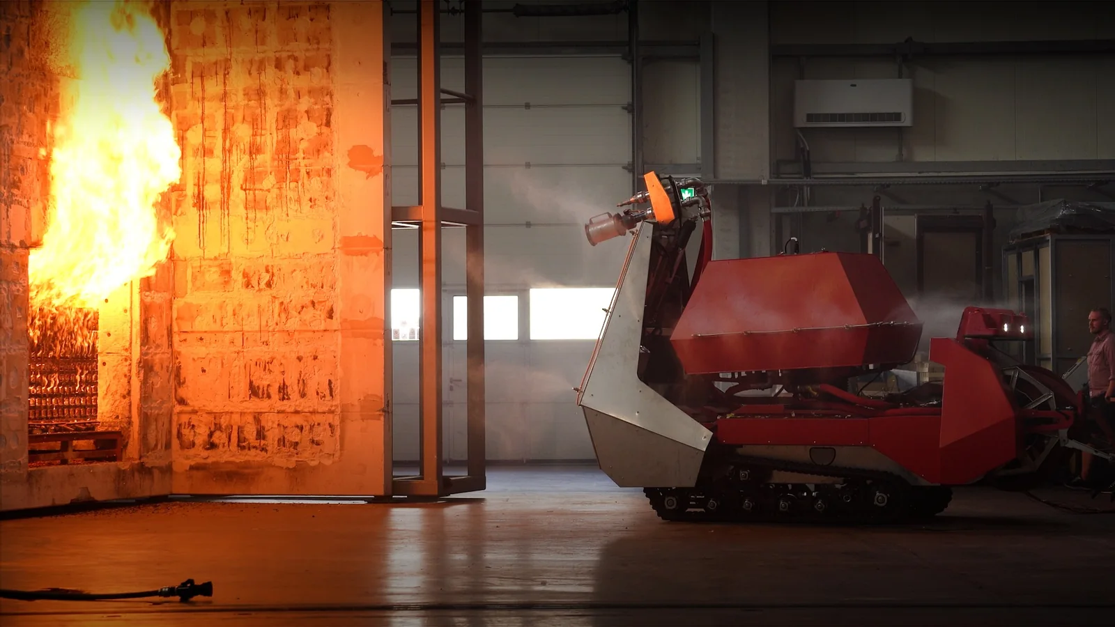
Časovnica preizkusa toplotnega sevanja
Preizkus se je začel na večji varni razdalji, nato pa se je FFRS v nadzorovanih korakih približeval. Spodnja časovnica prikazuje razdaljo, izmerjene temperature in dejanja operaterja med preizkusom.
| Pretečeni čas | Razdalja od vira toplote | Meritev / dejanje |
|---|---|---|
| Začetek | 7 m | Preizkus toplotnega sevanja se je začel z FFRS na razdalji 7 m od vira ognja in aktivnim merjenjem s termočleni. |
| 6 min | 6 m | FFRS je bil premaknjen na 6 m. Termočleni so pokazali približno 40 °C, pri čemer je temperatura ostala stabilna in ni več naraščala. |
| 9 min | 5 m | FFRS je bil premaknjen bližje na 5 m, da bi se povečala toplotna izpostavljenost. |
| 14 min | 5 m | Izmerjena temperatura je dosegla približno 90 °CTakrat je bil aktiviran vodni ščit, po čemer se je izmerjena temperatura znižala za približno 15 °C. |
| 21 min | 4.5 m | FFRS je bil premaknjen še 0,5 m bližje viru ognja, da bi povečali toplotno obremenitev in se ponovno približali ciljni temperaturi 90 °C. |
| 22 min | 4,5 m → 6 m | Približno 90 °C je bilo izmerjeno na spodnjem delu ščita. Vozilo je bilo premaknjeno nazaj na 6 m. |
| 23 min | 6 m → 7 m | Temperatura termočlena je ostala pri približno 91 °C, zato je bil FFRS ponovno premaknjen nazaj na 7 m. |
| 30 min | 7 m | Preizkus se je po 30 minutah zaključil, ko je gorljiva kocka vira toplote dogorela. |
Odziv vodnega ščita
Najpomembnejši prehod se je zgodil pri 14 minutah. Na razdalji 5 m od vira toplote so termočleni izmerili približno 90 °C in aktiviran je bil vodni ščit FFRS. Po aktivaciji se je izmerjena temperatura znižala za približno 15 °C, kar prikazuje takojšen hladilni učinek, zabeležen med tem preizkusom.
Platforma je bila nato pri 21. minuti namerno ponovno premaknjena bližje, da bi povečali obremenitev s sevalno toploto. Minuto pozneje je bilo na spodnjem delu ščita izmerjenih približno 90 °C, nato pa je bil FFRS premaknjen najprej nazaj na 6 m in zatem, ker so termočleni pri 23. minuti še vedno kazali približno 91 °C, na začetno razdaljo 7 m.
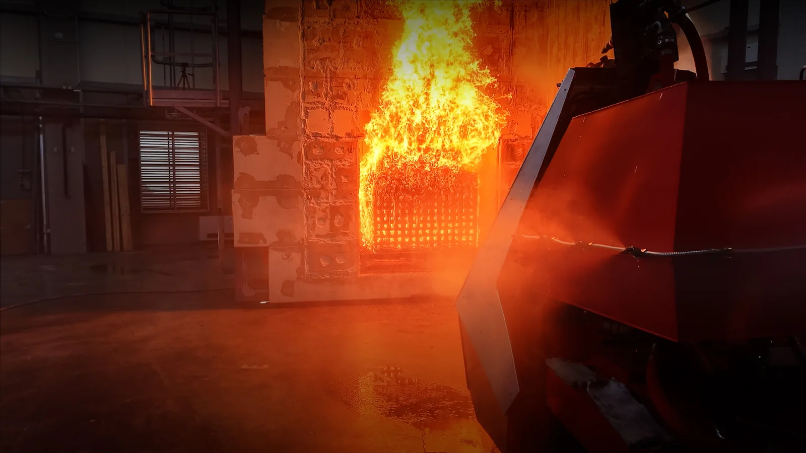
Poraba vode med preizkusom toplotnega sevanja
Vodni ščit je bil med 30-minutnim preizkusom uporabljen približno 16 minut Po tem obdobju delovanja vodnega ščita je bila raven vode v vgrajenem rezervoarju še vedno približno 95%. Po preizkusu je bil rezervoar ročno ponovno napolnjen do vrha. Vrednost 95 % predstavlja opaženo raven v rezervoarju po testnem zaporedju in je ni treba razumeti kot laboratorijsko kalibrirano meritev porabe pretoka.
FFRS je zaključil 30-minutno zaporedje preizkusa toplotnega sevanja z merjenjem termočlenov in nadzorovanimi spremembami varne razdalje. Na razdalji 5 m je temperatura dosegla približno 90 °C; aktivacija vodnega ščita je povzročila opaženo znižanje temperature za približno 15 °C. Po približno 16 minutah uporabe vodnega ščita je bila raven vode v vgrajenem rezervoarju približno 95 %.
Kaj oba preizkusa skupaj prikazujeta
Obe testni zaporedji obravnavata različna vidika robotskega gašenja. Preizkus razreda A se osredotoča na možnost daljinskega pozicioniranja FFRS in dokončanja naloge gašenja z določene varne razdalje. Preizkus toplotnega sevanja se osredotoča na nadzorovano izpostavljenost naraščajoči sevalni toploti, spremljanje temperature in odziv sistema vodnega ščita.
Preizkus razreda A prikazuje daljinsko gašenje, medtem ko operater ostaja ločen od neposrednega območja požara.
Sistem je bil uporabljen do popolne pogasitve, ne le za prikaz pretoka vode ali gibanja monitorja.
Pri preizkusu toplotnega sevanja so bili uporabljeni termočleni, ki jih je namestil ZAG, za spremljanje FFRS med spreminjanjem razdalje do vira toplote.
Pri približno 90 °C je aktivaciji vodnega ščita sledilo opaženo znižanje temperature za približno 15 °C.
Pomembne gasilske specifikacije FFRS
Naslednje objavljene specifikacije predstavljajo kontekst za platformo FFRS, uporabljeno pri preizkusih. Gre za splošne specifikacije platforme in jih ni treba razumeti kot meritve, zabeležene med posameznimi preizkusi, razen če je to izrecno navedeno v zgornjih rezultatih.
| Področje sistema | Objavljena specifikacija FFRS |
|---|---|
| Vgrajena voda | 1.500 l rezervoar za vodo |
| Pena | Ločen 170 l rezervoar za peno |
| Pretok vode | Do 340 l/min |
| Delovni tlak | Do 16 bar |
| Domet curka | Do 30 m |
| Daljinsko upravljanje | Do 1.000 m v vidni liniji |
| Termovizija | 640 × 480 LWIR |
Obseg in omejitve preizkusov
Kako je treba razlagati rezultate
- Rezultat 4 minute in 30 sekund velja samo za nadzorovani preizkus gašenja požara razreda A, prikazan v 1. delu.
- Meritve temperature, spremembe razdalje in opažanja vodnega ščita veljajo samo za ločen preizkus toplotnega sevanja, prikazan v 2. delu.
- Preizkusi ne predstavljajo vseh možnih velikosti požara, gorivnih obremenitev, geometrij, prezračevalnih ali okoljskih pogojev.
- Posnetki prikazujejo nadzorovano tehnično testiranje in ne nenadzorovane dejanske intervencije.
- Rezultatov ni treba razlagati kot certifikacijo po določenem standardu požarnega testiranja, razen če je takšna certifikacija posebej navedena.
- Objavljene specifikacije platforme FFRS so splošne sistemske specifikacije in ne izmerjene vrednosti posameznih preizkusov, razen kadar so izrecno označene kot testni podatki.
Nadzorovano testiranje je le del širšega procesa validacije. Dejanski incidenti lahko vključujejo dodatne spremenljivke, kot so veter, gostota dima, strupene snovi, konstrukcijska nestabilnost, komunikacijske omejitve in hitro spreminjajoče se toplotne obremenitve.
Del širše validacije FFRS
Preizkus gašenja razreda A in preizkus toplotnega sevanja skupaj zagotavljata dve različni vrsti dokazov o platformi FFRS: prvi se osredotoča na dokončanje daljinske naloge gašenja, drugi pa na spremljano toplotno izpostavljenost in odziv vodnega ščita. Ločena predstavitev rezultatov omogoča lažje razumevanje in preverjanje operativnih pogojev ter izmerjenih izidov.
Za širši pregled platforme si oglejte stran FFRS robotski sistem za gašenje požarov Za več informacij o daljinskem upravljanju in avtonomnih funkcijah si oglejte Daljinsko upravljani in avtonomni gasilski roboti.
Raziščite gasilski robotski sistem FFRS
Oglejte si celotno platformo FFRS, vgrajeni gasilni sistem, mobilnost, daljinsko upravljanje, termovizijo in predvidene uporabe za civilno zaščito ter posredovanje v nevarnih okoljih.
Raziščite gasilski robotski sistem FFRS